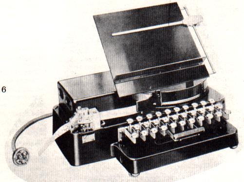
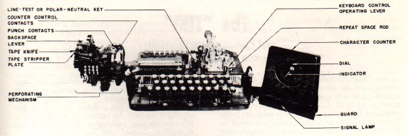
The Model 14 Reperforator was produced in numerous wiring configurations for both military and Bell System applications. The schematics presented here were scanned from War Department Technical Manual TM-11-2223, issued September 1947, and include all diagrams from that manual.
The principal differences between machines will be found in the motor type and the selector type. Pulling magnet selectors have round coils covered with black insulation resembling friction tape, or a greenish-grey insulating material; these are wired only in series and operated only on 60 milliamperes loop current. Holding magnet selectors are characterized by rectangular-shaped coils with “HM” stamped on the range finder; these offer series or parallel operation via a toggle switch or terminal strip, at either 20 or 60 milliamperes.
Synchronous motors are characterized by a fan mounted on the rear. Governed motors feature a black-and-white target assembly; speed is adjustable and set by viewing the target through a specially shuttered 87.6 VPS tuning fork. Running speed was typically 2100 RPM. The schematics are thirteen pages; they are scanned so that pages may be trimmed and taped together to reconstruct full-size drawings. Vertical registration is consistent.
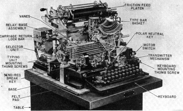
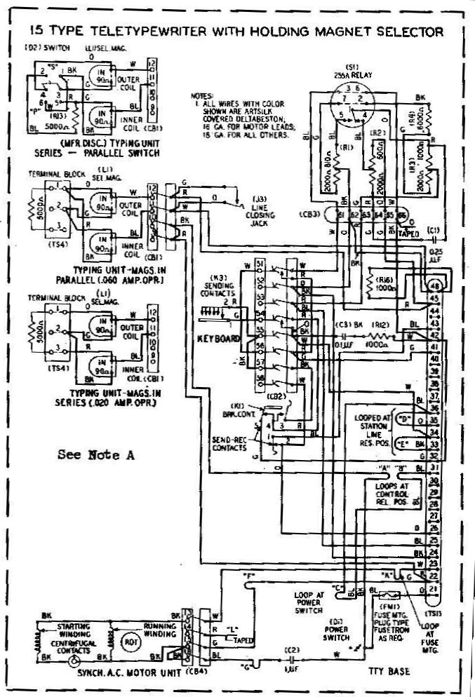
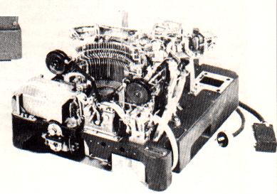
The Model 15 is a self-contained page printer with keyboard and motor. It uses a single magnet selector which can be operated direct from a terminal unit or through a polar relay. Two selector types exist: the pull type, which requires current to pull the selector back after each operation; and the holding type, which mechanically returns the selector after each operation. Both types can be operated with the two coils in series or parallel for 30 or 60 milliampere operation.
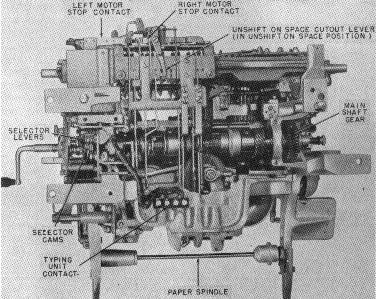
The paper is held on a roller that does not move laterally; the type basket travels from left to right as copy is received. The range finder is located on the left side and is adjustable through a small door. An unshift-on-space cut-out lever is provided under the front of the printer — of particular value when copying weak DX signals, as it prevents a static pulse on the shift line from putting the machine into upper case.
The keyboard has the standard distribution assembly shared with the Models 12, 14, 19, 24, and 26. The coil and condenser across the keyboard contacts must be removed for direct FSK operation, though it may be left in place when a polar relay is used, to reduce RF noise from the contact break.
Normal amateur operation is at 60 WPM using gear wheels numbered 74912 and 74913. The selector magnet terminals 41 and 42 are used for the printer in a direct connection setup. For polar relay installations, specific wiring changes are required as described in the original documentation.
Optional features available on some machines include automatic carriage return and tab function (upper case G). A keyboard perforator can replace the standard keyboard, making the 15 similar in capability to a Model 19, though this requires a 500 milliampere, 110-volt DC power supply.
The Model 19 combined a keyboard send-receive printer with an integrated perforator-transmitter, making it the standard workhorse of amateur RTTY for many years. The set included a motor-driven transmitter distributor (TD) and a separate rectifier unit (REC-30).
Diagrams available include the typing unit, base, and relay schematic and wiring; the perforator-transmitter schematic and actual wiring; the REC-30 rectifier schematic and actual wiring; the Model 19 table schematic and actual wiring; and the Model 14 Transmitter-Distributor wiring diagram.
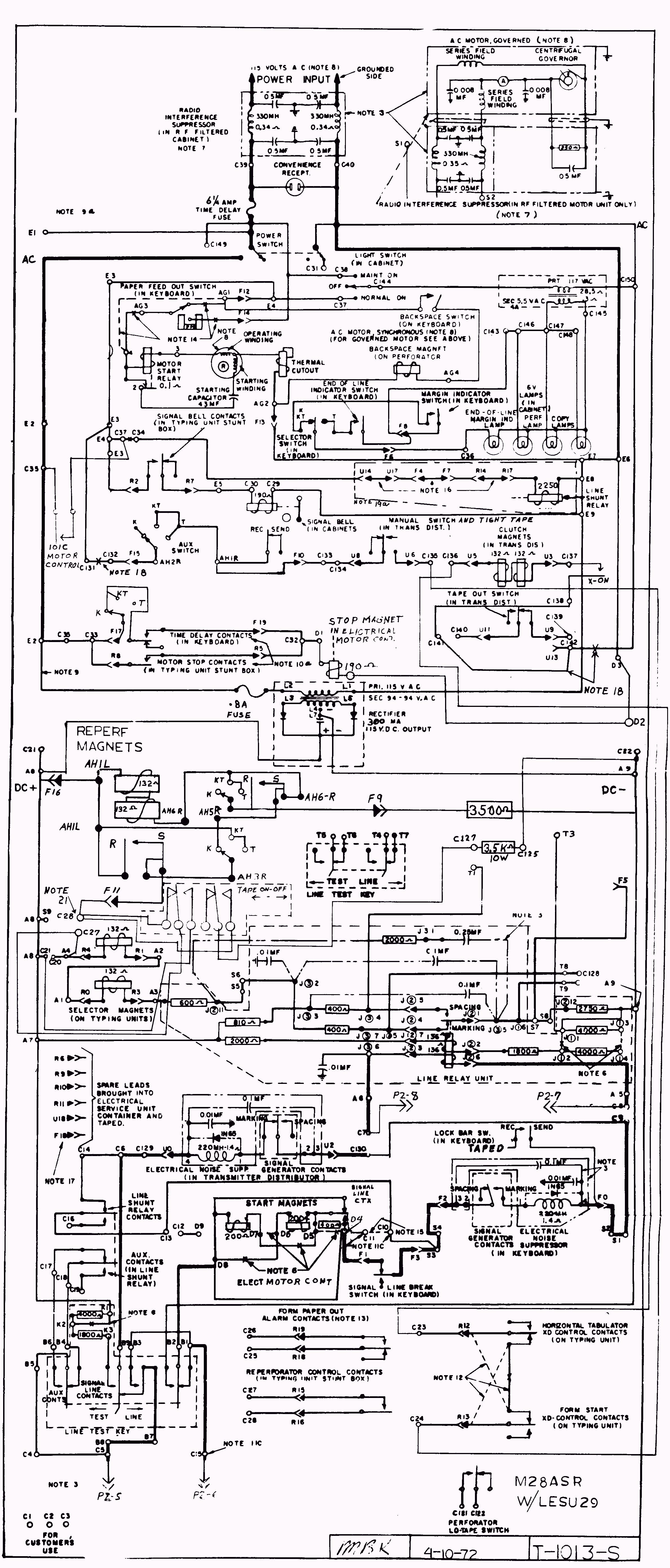
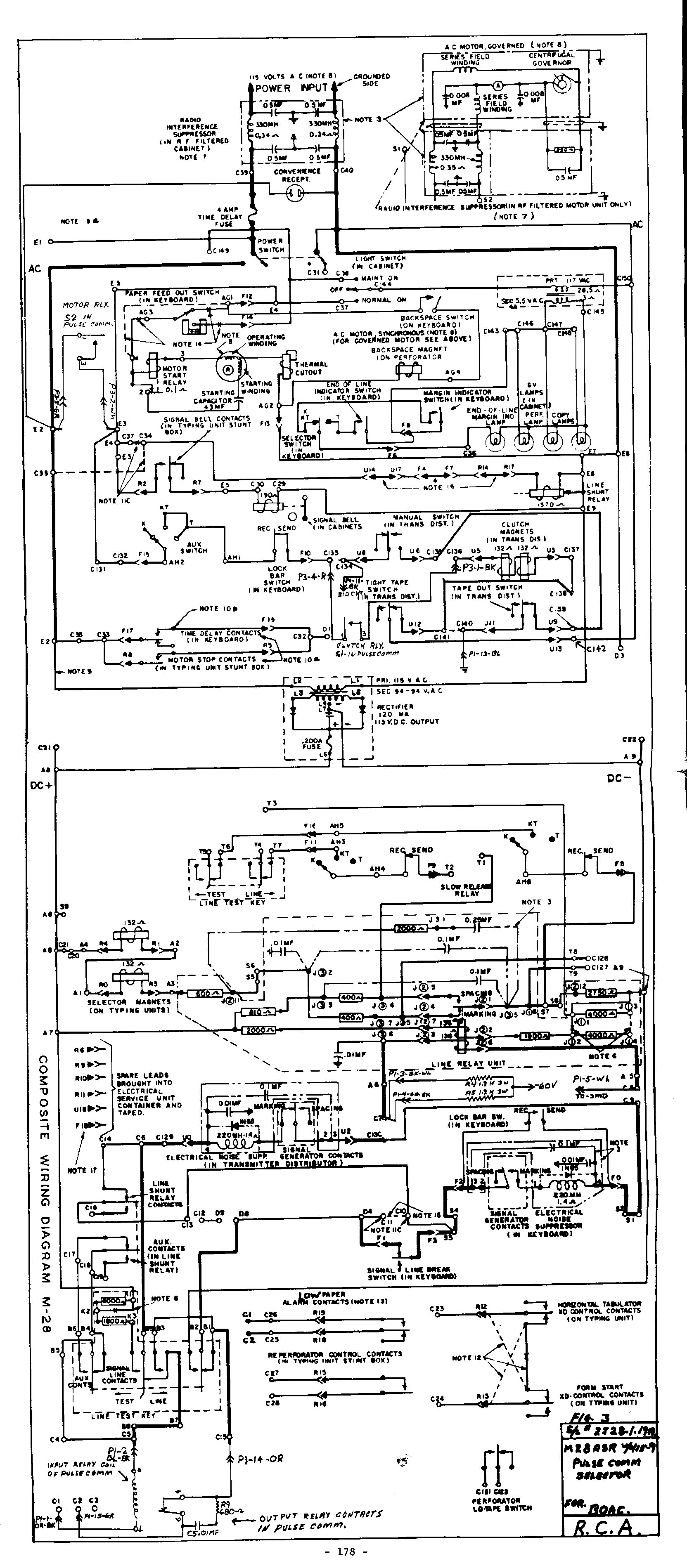
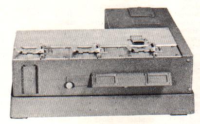
The Model 28 ASR (Automatic Send-Receive) is the machine most commonly encountered in amateur RTTY. It combines a keyboard printer, paper tape punch (reperforator), and tape reader in a single unit, allowing unattended transmission from pre-punched tape as well as simultaneous send-receive operation.
The Model 28 was designed for adaptability across a wide variety of installations. A number of wiring options were available; Bell System shop personnel would wire in the desired configuration and cross out unused options in crayon directly on the wiring diagrams, which were typically stored in the base of the machine.
Electrical drawings are available for four configurations, each covering a different ESU (Electrical Service Unit) type. Images open at 640×400 for on-screen viewing; high-resolution JPG versions (approximately 1 MB each) are available for printing at full scale.
These are Teletype Corporation and Western Electric shop diagrams, typically found in the base of machines from telco installations. The Model 28 was designed for a large variety of installation options; shop personnel wired in the desired options and crossed out those not installed. The cross-outs on individual drawings are part of the record — the information is present regardless.
Drawings are in PDF format, scanned to allow paper-doll trimming and taping so that complete full-size drawings can be reconstructed. There is some intentional overlap between drawings to facilitate this. When printing, use Shrink to Fit to avoid cropping the left and right edges.
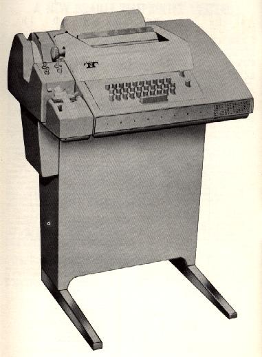
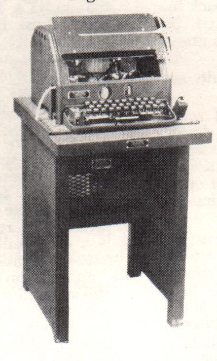
Of all the various Teletype models in amateur use, no single unit offers all the features found in the 32 ASR. It provides facilities for transmission or reading of perforated tape, and for page copy from either the local loop or a terminal unit. The 32 ASR may be used for keyboard transmission with simultaneous page copy and optional tape perforation; tape reader transmission with page copy; or keyboard tape perforation with page copy.
Dimensions: 22″ wide, 18½″ deep, 8⅜″ high, approximately 44 lbs. The stand adds 24½″ in height and 12 lbs. The unit is finished to match contemporary amateur radio equipment styling.
The printer differs significantly from earlier Teletype printers. The type-wheel is rotationally and vertically positioned to select the character; a small hammer drives it against the ribbon and paper. Automatic carriage return and line feed occur after the 72nd character. Unshift on space is built in.
The selector magnet requires 500 milliamperes at 20 volts, supplied by a printed circuit selector magnet driver card. The input can be strapped for 20 or 60 milliampere operation by a strap change on the rear terminal strip. A “here is” key provides automatic identification using a 22-character code drum; characters are coded by breaking off plastic tines. The tape reader is electrically operated via the same PC distributor used by the keyboard, making it notably quiet.
The motor is a two-pole single-phase synchronous motor at 3600 RPM with two internal fans and one external fan. Nylon gears and a flexible belt provide very quiet operation.
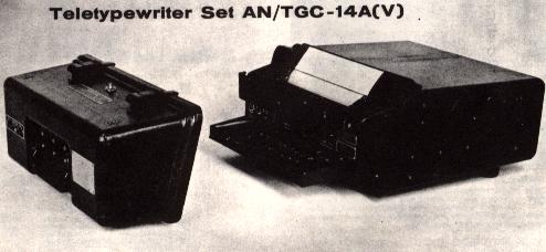
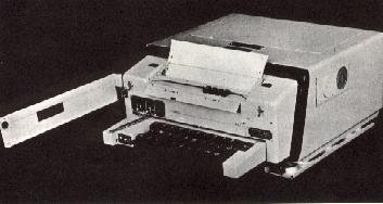
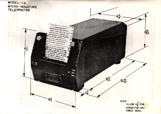
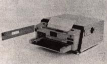
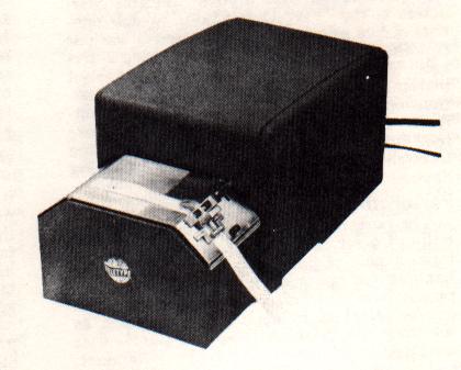
The MITE (AN/TGC-14A(V)) is the first miniaturized mobile send-receive teletypewriter designed specifically for military tactical use. It transmits and prints page copy at 100 words per minute under adverse environmental and tactical conditions, and can be set up to operate within one minute of connection to a power source — whether on the ground, in aircraft, or in armored vehicles.
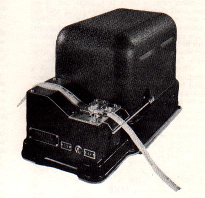
The unit is modular in construction for easy access and inspection, and weighs approximately 36 pounds complete with transmitting keyboard, receiving page-printer, connecting chassis with internal line battery supply, and airborne-type case with shock mounting. It is designed and qualified to MIL-E-5400 and MIL-E-16400 specifications, withstanding severe shock, vibration, dust, and salt spray atmosphere.
All units use solid-state electronic line sensing in lieu of conventional electromechanical relays, improving operating characteristics and service life. Self-contained heaters allow operation at ambient temperatures as low as −54°C with less than 40 minutes warm-up time.
Related variants include the TT-264/AG (air-to-air and ground-to-ground), TT-299A/UG (shipboard and submarine), and TT-395/UG (general communication use). Receive-only versions (TT-298A/UG and TT-394/UG) are mechanically identical to their send-receive counterparts and can be converted to full capability by insertion of the keyboard without tools.
Tape equipment provides the most rapid and reliable means of handling traffic on amateur frequencies. It permits preparation of a reply while receiving from another station, makes even the slowest typist sound experienced, and enables bulletins and net rosters to be sent accurately at full machine speed.
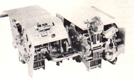
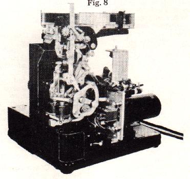
The Transmitter Distributor (TD) is a motor-driven device which translates code combinations perforated in paper tape into electrical impulses and transmits them to one or more receiving stations. Two kinds exist: five-unit code and six-unit code (the latter accommodating wider tape and one additional impulse).
The tape sensing mechanism uses contact levers that pivot on a shaft and have extensions carrying tape pins; these enter code holes in the tape as the operating cam rotates. The distributor completes connections to the signal line in sequence at constant speed via brushes traversing segments and a collector ring.
The Model 14 TD (L4TD) is the most commonly encountered unit in amateur use. Nine figures illustrate the mechanism and its components.